Bolt Flange Size Chart
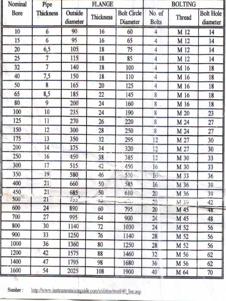
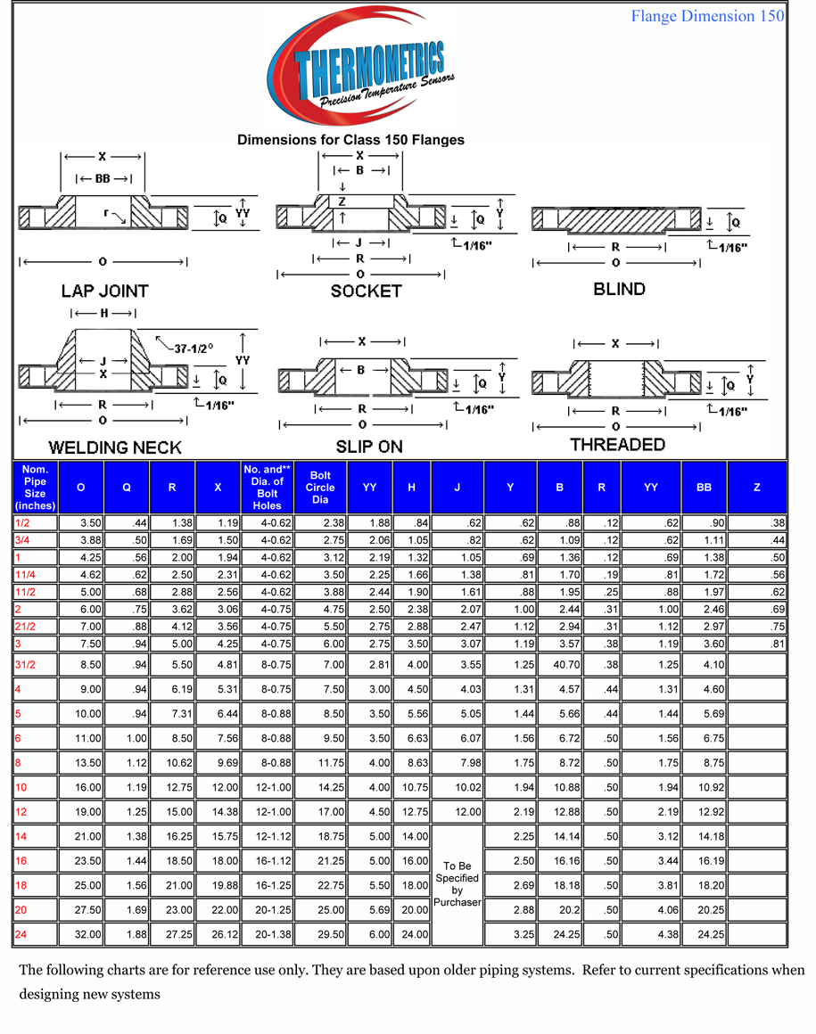
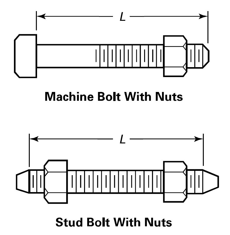
Bolt Flange Size Chart - Flange dimensions are determined by the pipe size and the pressure class required for the application. Web explore the comprehensive flange bolting chart at texas flange. Dn = diameter nominal (size) a = flange. D1 = diameter of bolt circle. Web instant flange bolt sizes and torque patterns: When ordering, allow for the total length required for all components. Web pipe flange size & bolt chart. Web ansi standard hardware menu. B = thickness of flange. This is for informational purposes only. Web below is asme b16.5 150#, 300#, 600# stud bolt flange chart information that can assist engineers and pipe fitters with calculating the number of fasteners associated according to flange size. The lengths of the machine bolts are measured from under the head to the top of the bolt. This is for informational purposes only. Web the following ansi flange charts & flange tables provide flange dimensions including, flange overall diameters, number of bolts and bolt size for the most common sizes of ansi flanges for ratings from ansi 150 through to ansi 1500. 1500# flange bolt chart with length & diameter of studs, pipe size, and wrench size. Access essential information for secure and reliable connections in your piping projects. Web the following is chart data for ansi b16.5 flange dimensional data size table for 1/2 to 2 1/2 inches. Asme flange bolting (number, diameter, length of stud bolts by asme flange sizes); Web pipe flange size & bolt chart. Stud bolt torque chart (tightening sequence and load to ensure proper flanged joints) The following is chart data for ansi b16.5 flange dimensional data table for sizes 3 to 10 inches. N = number of bolts. Nominal pipe size nps (inches) outside diameter of flange (inches) no. Access essential information for secure and reliable connections in your piping projects. Web instant flange bolt sizes and torque patterns: Limitation of liability and disclaimer of warranty: The lengths of the machine bolts are measured from under the head to the top of the bolt. D1 = diameter of bolt circle. D1 = diameter of bolt circle. Dn = diameter nominal (size) a = flange. B = thickness of flange. Web 300# flange bolt chart with length & diameter of studs, pipe size, and wrench size. D1 = diameter of bolt circle. Web the following chart shows the quantity and size of bolts or studs require for a particular flange size and class. Nominal pipe size nps (inches) outside diameter of flange (inches) no. Asme flange bolting (number, diameter, length of stud bolts by asme flange sizes); B = thickness of flange. Web ansi standard hardware menu. Class 900 number of bolts. D1 = diameter of bolt circle. Web 300# flange bolt chart with length & diameter of studs, pipe size, and wrench size. Web instant flange bolt sizes and torque patterns: Asme flange bolting (number, diameter, length of stud bolts by asme flange sizes); Class 900 number of bolts. N = number of bolts. Web flange dimensions charts listed by nps and by flange class. Class 900 number of bolts. N = number of bolts. Web 150# flange bolt chart with length & diameter of studs, pipe size, and wrench size. 1500# flange bolt chart with length & diameter of studs, pipe size, and wrench size. Web flange dimensions are covered in the following tables of asme b16.5 2020: Web the following is chart data for ansi b16.5 flange dimensional data size table for 1/2 to 2 1/2 inches. Web in this article, i have covered flange bolt dimension chart and stud size dimensions for stud and bolt used in piping. D2 = diameter of raised. Web reading a flange bolt size chart is fairly straightforward. In no event will south coast industrial metals or any of its affiliates be liable for any damages arising from the use of the information included in this document or that it is suitable for the ‘applications’ noted. Dn = diameter nominal (size) a = flange. Bolts diameter & length. Flange dimensions are determined by the pipe size and the pressure class required for the application. D2 = diameter of raised face. Size (inches) number of bolts diameter of bolt stud bolt length machine bolt length number of bolts diameter of bolt stud bolt length 112 1/2 2 1/4 1/2 2 1/2 2 1/4 1/2 1/2 1/2 3/4 4.25 3/4. In no event will south coast industrial metals or any of its affiliates be liable for any damages arising from the use of the information included in this document or that it is suitable for the ‘applications’ noted. Web flange dimensions are covered in the following tables of asme b16.5 2020: Web class 150 flanges bolting pattern & bolt sizes.. Web the following ansi flange charts & flange tables provide flange dimensions including, flange overall diameters, number of bolts and bolt size for the most common sizes of ansi flanges for ratings from ansi 150 through to ansi 1500. The following is chart data for ansi b16.5 flange dimensional data table for sizes 3 to 10 inches. Bolts diameter & length nom pipe size no. Stud bolt torque chart (tightening sequence and load to ensure proper flanged joints) Web 300# flange bolt chart with length & diameter of studs, pipe size, and wrench size. Web reading a flange bolt size chart is fairly straightforward. N = number of bolts. When ordering, allow for the total length required for all components. Web ansi standard hardware menu. Web pipe flange size & bolt chart. The lengths of the machine bolts are measured from under the head to the top of the bolt. Dn = diameter nominal (size) a = flange. Web the following chart shows the quantity and size of bolts or studs require for a particular flange size and class. We hope pipeline engineers will find this information on flange bolt sizes and lengths useful. This is for informational purposes only. B = thickness of flange.Printable Flange Size Chart

Ansi Flange Bolt Length Table

Technical Info Flange BoltUp Charts

Flange Bolting Chart Texas Flange
Bolt Size Flange Chart
ANSI Flange Bolt Chart
Flange Bolting Chart ASME B16.5

150 Flange Bolt Sizes
Flange Size Guide Printable
Flange Bolt Dimensions Chart and Stud Size in mm
Nominal Pipe Size Nps (Inches) Outside Diameter Of Flange (Inches) No.
Web Key Charts For Stud Bolts:
Web Class 150 Flanges Bolting Pattern & Bolt Sizes.
Below Are Flange Bolting Charts Containing Specifications For Class 150 Flanges, Class 300 Flanges, And Class 600 Flanges.
Related Post: